

Location
Coatesville, Pennsylvania
Structure Type
A new concrete retaining-wall foundation (roughly 10 to 13.5 feet wide) supporting a high-level passenger rail platform, beside active electrified tracks
Core Challenge
Excavation exposed loose silty sand and sandy silt below the planned footing that could not meet the required bearing, in a narrow rail corridor where over-excavation was limited to one foot and widening the footing was not an option
Verification
A sealed engineering calculation of the composite soil-and-polymer bearing capacity, with installation performed under continuous laser monitoring (about 1 mm resolution) and stop criteria to prevent lifting the new concrete
URETEK Scope
Design and injection of a two-component, water-resistant expanding structural polymer through preinstalled 2-inch sleeves on a roughly 3-by-3-foot grid, treating the soil at multiple elevations to about 10 feet
Result
The sealed calculation put the improved soil-polymer mass at a weighted-average allowable bearing capacity of 2,551 psf, meeting the 2,500 psf design requirement, achieved within the existing footprint with no wider footing and no over-excavation beyond the one-foot limit
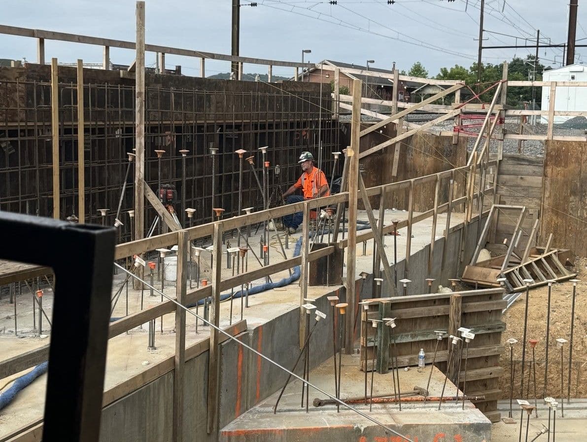
Ground improvement beneath a new retaining-wall footing in a deep, support-braced excavation beside active electrified tracks, where a wider footing and deeper over-excavation were not options
A new high-level passenger platform was being built as part of a rail-station improvement program, and along the active tracks its retaining wall needed a foundation roughly 10 to 13.5 feet wide, running about 386 feet. When the excavation was opened, the soils at the bottom of the footing did not provide the bearing the design required.
The subsurface told the story. Borings and bottom-of-footing samples characterized the zone as loose silty sand and sandy silt, with corrected penetration values from the low single digits into the mid-teens, roughly 44 to 45 percent fines, and moisture contents near 18 to 20 percent. In short, the soil under the planned wall was too loose and too fine to carry the load as it was.
The corridor left little room to maneuver. The wall sat close to active electrified tracks inside a temporary support-of-excavation system; the design limited routine over-excavation to a single foot; and widening the footing was not recommended because the space was tight and a larger footprint could conflict with adjacent infrastructure. The project needed a way to strengthen the soil in place, beneath the planned footing, without enlarging the hole or the foundation, and without disturbing freshly placed concrete.
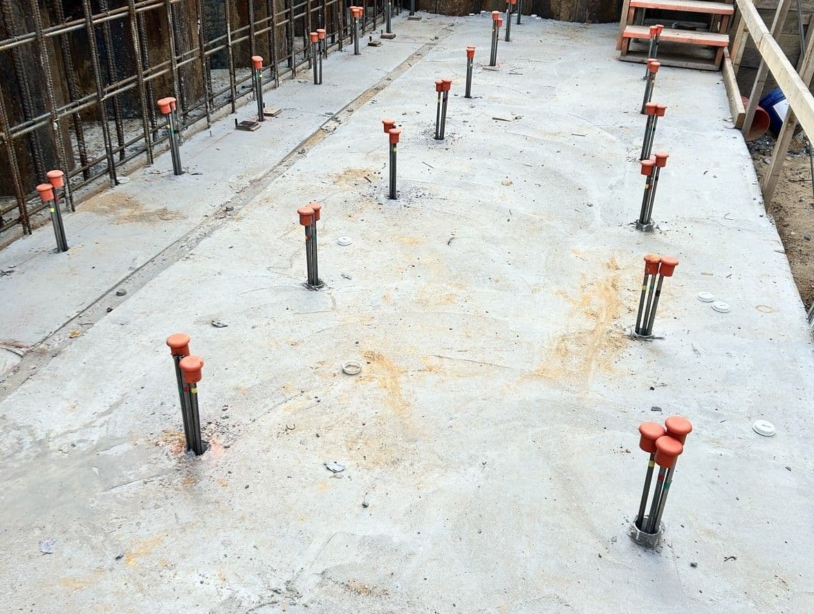
Preinstalled 2-inch sleeves cast through the footing on a roughly 3-by-3-foot grid: the layout gave the crew repeatable access to inject the soil at depth without drilling through the finished concrete
Each obvious alternative ran into the site. Deeper over-excavation and replacement would have needed an exception to the one-foot limit and more work inside the temporary shoring. Widening the footing was off the table in the narrow corridor, with adjacent infrastructure close by. Micropiles were an acceptable deep-foundation option, but they would have changed the load-transfer strategy and added deep elements next to active rail.
What the alternatives had in common was that they changed the excavation or the foundation to work around the weak soil. The more direct move was to fix the soil itself, in place, beneath the footing as designed.
That is what engineered expanding-polymer ground improvement offered: treat the bearing zone through small access points, within the planned footprint, and carry it forward on a documented design basis. The method was selected for detailed design and installation.
The access was designed before the concrete was placed. Two-inch sleeves were cast through the footing at the planned injection points (installed by others ahead of URETEK), so that after the concrete cured, thin steel tubes could be advanced through the sleeves to reach the soil. That preserved repeatable access to every treatment point without drilling large openings through the finished foundation.
Working on a roughly 3-by-3-foot grid, crews advanced the tubing through each sleeve and injected a two-component, water-resistant expanding structural polymer at multiple elevations to a planned depth of about 10 feet. The two liquids combined at the tip and expanded within the confined soil, filling accessible voids and applying expansion pressure to the surrounding ground.
The improvement was engineered as a composite. The existing soil remained the primary material, while cured polymer occupied a calculated share of the treated volume, filled voids, and applied expansion pressure to the surrounding ground, raising the bearing capacity of the mass as a whole.
Because the objective was support and not lift, the work was controlled to protect the new concrete. The plan required rotating laser levels and receivers able to detect about one millimeter of movement, and each injection was to stop if any upward movement was seen before the planned quantity was placed. Flow meters or recorded pump strokes tracked the amount injected at each point and kept the two components in the correct ratio. When treatment was complete, the steel tubes were cut flush and the sleeve openings were closed with non-shrink grout.
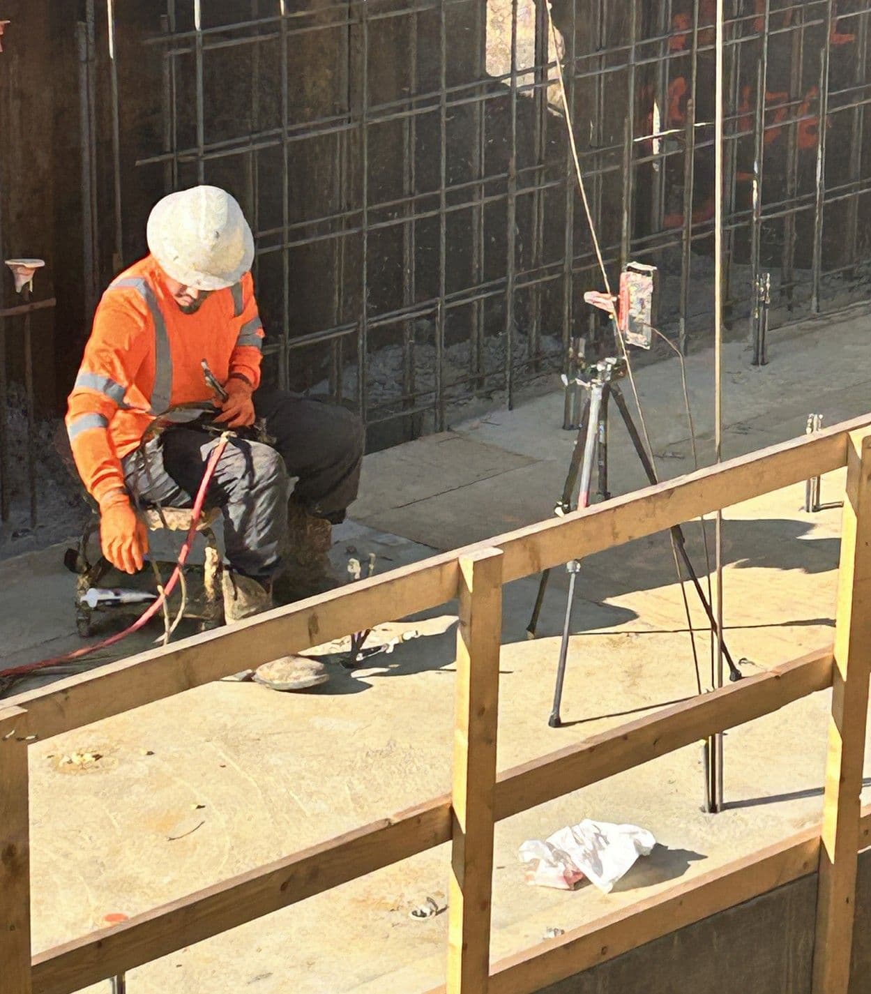
Injecting the expanding polymer through a sleeve while a laser level monitors the footing: the crew stopped at any sign of upward movement, improving the soil without lifting the new concrete
This project's result is an engineering design basis, not a field load test, and the numbers behind it come from the sealed ground-improvement calculation and the geotechnical data it drew on.
The starting point was the unimproved soil: the loose silty sand and sandy silt were assigned a presumptive allowable bearing pressure of about 1,000 psf, well short of the 2,500 psf the foundation required. The calculation then estimated the confined strength of the cured polymer at the treatment depths and applied a factor of safety, arriving at an allowable bearing capacity of about 10,122 psf for the polymer itself.
Combining the two as a composite, the analysis modeled the treated zone as roughly 83 percent existing soil (at 1,000 psf) and 17 percent cured polymer (at 10,122 psf), for a weighted-average allowable bearing capacity of 2,551 psf. That is the engineered design value for the improved soil-polymer mass, and it clears the 2,500 psf requirement by about 51 psf.
It is worth being precise about what that figure is. The 2,551 psf is a sealed engineering calculation for the proposed improved ground, supported by dated field photographs of the sleeve layout, the injection work, and the monitoring setup. The available records do not include an independent post-treatment load test or long-term settlement monitoring, so the value is a design basis rather than a measured field result.
The engineered approach met the bearing requirement on paper, within the corridor's tight constraints, without changing the excavation or the foundation.
 Bearing requirement met in the sealed calculation. The composite soil-and-polymer analysis produced a weighted-average allowable bearing capacity of 2,551 psf against the 2,500 psf design requirement, a documented design basis rather than a field load test.No wider footing, no extra over-excavation. Because access was preplanned through embedded sleeves, the improvement stayed within the designed footprint and respected the one-foot over-excavation limit, avoiding a larger footing beside the tracks.The weak zone was treated at depth. Injection on a roughly 3-by-3-foot grid reached multiple elevations to about 10 feet, addressing the loose silty soils identified beneath the footing.The new concrete was protected. Laser monitoring at about one-millimeter resolution, with stop-on-movement criteria and tracked injection quantities, kept the work to soil improvement rather than lifting the foundation.Documented, and honest about its limits. Dated photographs record the sleeve layout, the injection, and the monitoring; the design basis is the sealed calculation, and no post-treatment load test or long-term monitoring is claimed.
Coordinate injection access before the concrete is placed. Casting sleeves through the footing on the treatment grid preserved repeatable access to the soil and avoided invasive drilling through finished concrete later.
Design to the real constraint set. The method was chosen because it improved the bearing soil while respecting the one-foot excavation limit, the fixed footing width, and the demands of working beside active electrified tracks.
Keep calculated capacity distinct from field verification. A sealed composite-bearing calculation is a defensible design basis, and it should be presented as exactly that, separate from a post-treatment load test, which was not part of this record.
Monitor the structure, not just the material. Laser monitoring and explicit stop criteria aligned the injection with the real objective, improving support without lifting the freshly placed foundation.
When weak soils turn up beneath a foundation and deeper excavation, a wider footing, or deep-foundation elements create conflicts, engineered expanding-polymer ground improvement can offer another option: strengthen the bearing soil in place, through small access points, on a documented design basis. URETEK's engineering team will review the geotechnical data, structural loading, access, and verification requirements, then design a treatment layout that fits the constraints of your site.

 800-240-7868


