

Location
Southeast Texas
Structure Type
A 14-foot-deep precast concrete sanitary sewer manhole. The 33-inch main line inlet and outlet had been sliplined to 27 inches, with two 10-inch inlets entering about 6 feet below grade.
Core Challenge
Inflow and infiltration through the manhole structure was putting groundwater and stormwater into a sanitary system built to carry neither. Replacing the affected structures priced out of reach, so the utility needed to know whether rehabilitation would hold before committing to a program.
Verification
Interior inspection to locate each point of water entry before injection, reinspection of the structure afterward, and a post-treatment data sheet logging every repaired defect and injection location.
URETEK Scope
URETEK Deep Injection (UDI) through 5/8-inch ports drilled through the manhole wall on a pattern set by the inspection, placing expanding polyurethane resin on the exterior face of the structure.
Result
One test manhole sealed and back in service within hours. The utility awarded a maintenance contract on the strength of it, and the project account reports dozens of additional manholes rehabilitated in the years since.
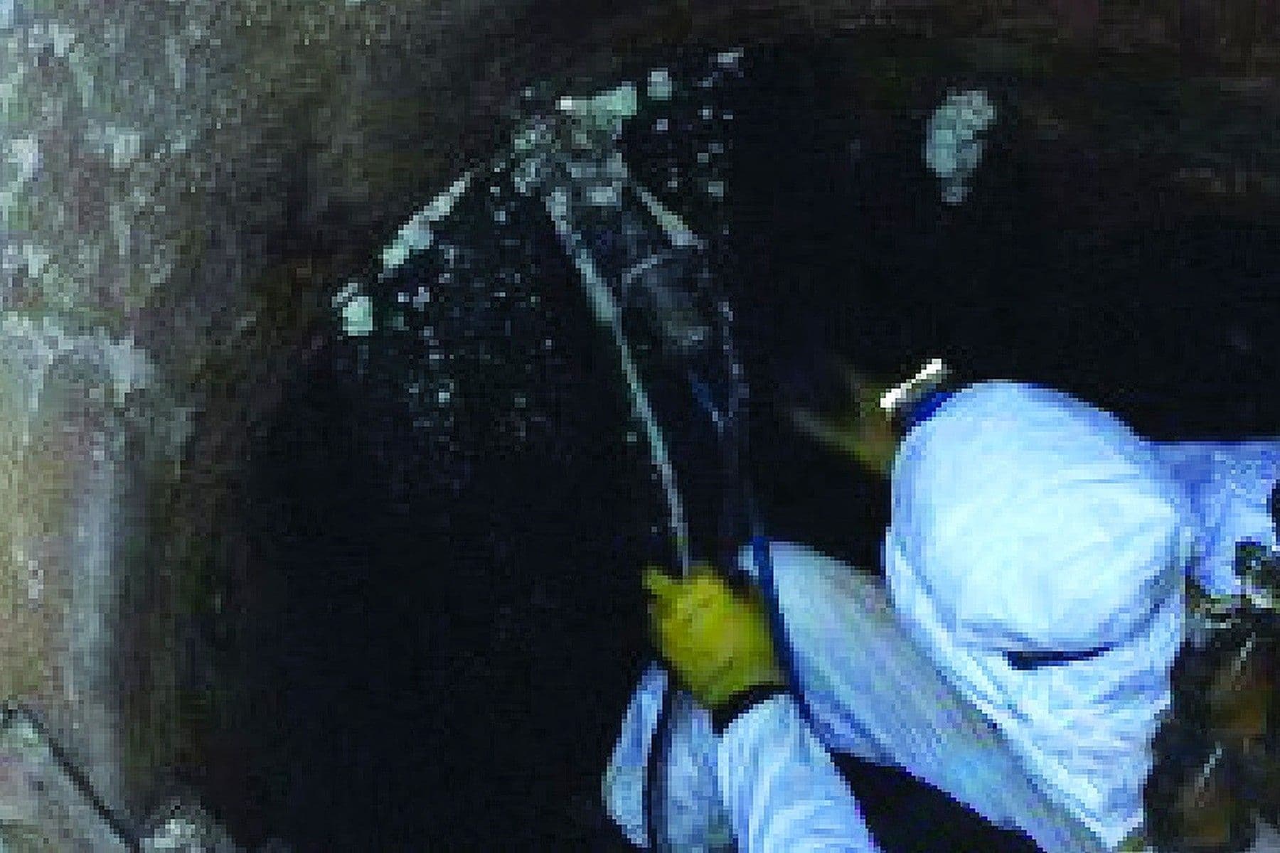
A technician injecting at an active point of entry inside the structure. On manhole work the water shows you where to drill.
A municipal wastewater utility had sanitary sewer manholes taking on inflow and infiltration. I&I is groundwater and stormwater finding its way into a pipe network sized and permitted for sewage, and every gallon of it occupies capacity that belongs to something else.
The downstream cost is what turns that into an operations problem. Excess flow raises the volume the utility pumps and treats, and in wet weather it is what pushes a collection system toward overflows and backups. Those are the general risks that drive I&I programs; the project record for this location does not document that any of them occurred here.
Replacement was the obvious remedy and the one the utility could not sign off on across the number of structures involved. That is the position that produces a pilot. The city chose one manhole that fairly represented the rest and used it to evaluate whether rehabilitating the existing structures was feasible at all.
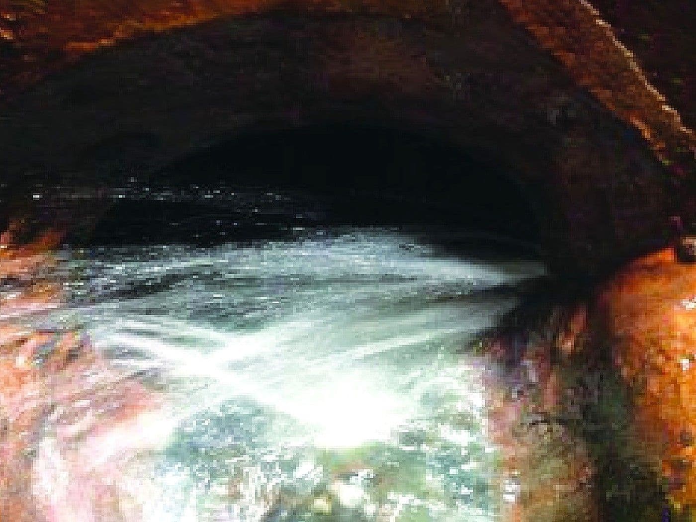
Groundwater under head coming through the wall of a structure. Water moving like this carries soil with it, which is how the void behind the wall gets there.
Full replacement of a 14-foot precast manhole means excavation, traffic control, handling the flow, a new structure, and backfill. Multiply that by a list of structures and the number stops being a maintenance line item.
Rehabilitating what was already in the ground was the cheaper path on paper. The open question was whether a rehabilitation method would actually stop the water in these structures, in this soil, under this groundwater. Product literature does not answer that for a specific collection system, and the utility was being asked to fund a program on the answer.
So the evaluation got scoped down to one structure: a 14-foot precast manhole with a 33-inch main line sliplined to 27 inches at the inlet and outlet, and two 10-inch inlets about 6 feet down. One manhole, one crew visit, and a result the utility could look at before deciding anything else.
URETEK Deep Injection (UDI) treats a leaking manhole through the wall it already has. Crews drill small ports through the structure and place expanding polyurethane resin on the exterior face, where it fills the water pathway and the soil voids the water has already opened behind it. Nothing gets excavated, and the structure stays where it was built.
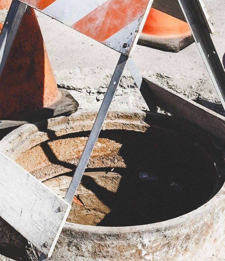
The test structure opened for the work. A 14-foot precast manhole, treated from the inside, with no excavation around it.
Crews went into the manhole and examined the interior for potential points of I&I, working the joints, the pipe connections, and the wall itself. Every point of ingress that inspection turned up went onto an injection layout. That layout is most of the job. A manhole leaks at particular places, and a pattern drawn from an actual inspection puts resin at each of them and keeps it out of sound wall.
Crews then drilled 5/8-inch holes through the manhole wall on that pattern and injected resin through each one. The material expanded and reached about 90% of its strength within 15 minutes of injection, sealing the treated pathways on the exterior face of the wall and filling the adjacent soil voids that earlier infiltration had opened. The hole diameter matters on a structure this size: 5/8 inch takes almost nothing out of a wall that has to keep doing its job afterward.
After treatment the crew reinspected the manhole and logged every repaired defect and injection location on a post-treatment data sheet. On a water-cutoff scope that record earns its keep. It tells the next inspector what was treated and where to look first if water shows up again, and it is the difference between a repair and a maintained asset.
Two limits belong on the record. Verification here was visual and documentary, with no before-and-after leakage or flow measurement and no long-term follow-up inspection in the available documentation. And sealing the walls addresses groundwater entering through the structure, which leaves surface inflow through the cover and frame as a separate assessment with a separate fix.
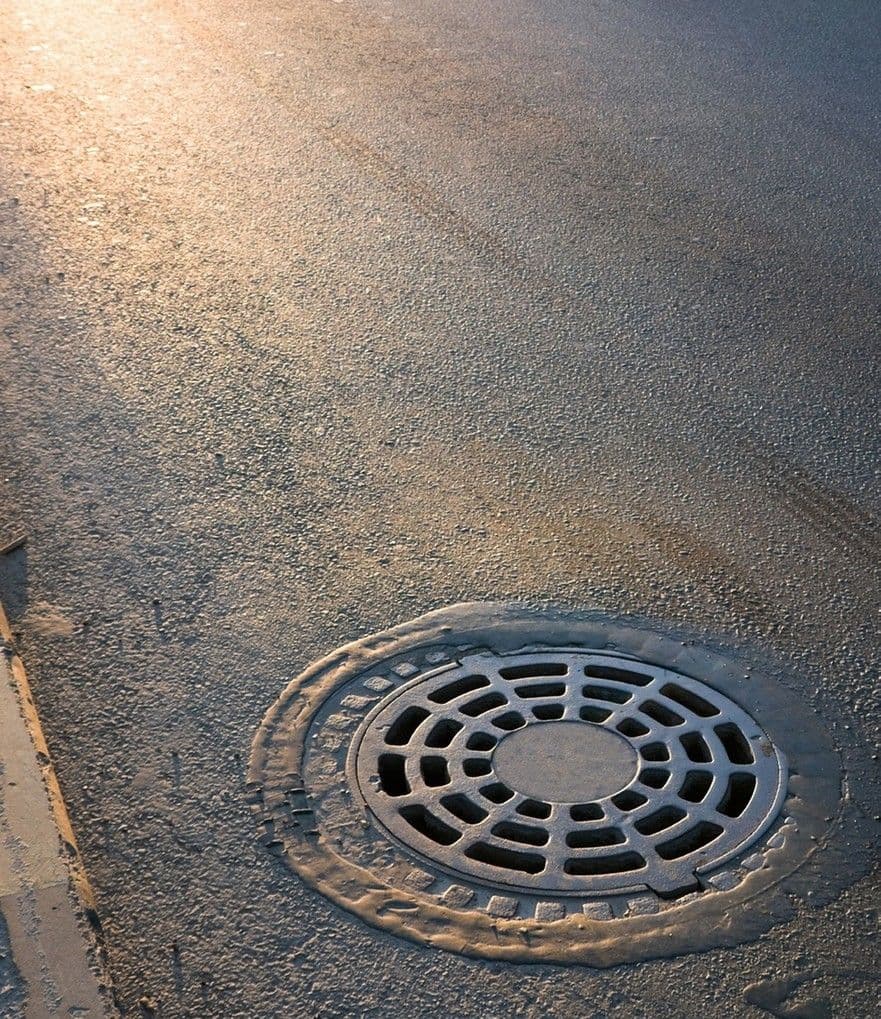
The structure back under traffic. The manhole returned to service the same day the work was done.
This is an inspection and production record. There is no quantified leakage rate here, no before-and-after flow comparison, and no long-term follow-up inspection, and the case for the method rests on what the crew observed at the structure and on what the utility did next.
On the structure: 14 feet deep, precast, a 33-inch main line sliplined to 27 inches at the inlet and outlet, and two 10-inch inlets about 6 feet below grade. Injection ports at 5/8 inch, drilled on a pattern set by the interior inspection rather than a standard radial layout.
On the schedule: the work was complete within hours, and the manhole was returned to service immediately afterward with no excavation around it.
On what followed: the utility awarded URETEK a maintenance contract on the strength of this one structure, and the project account reports dozens of additional manholes rehabilitated in the years since. A repeat order sustained across years is the outcome measure this record genuinely supports.
URETEK sealed a 14-foot precast sanitary manhole from the inside in a single visit, and the utility turned that one result into a standing rehabilitation program.
 Every identified point of entry treated. The interior inspection located each point of I&I in the structure, and the injection pattern was drawn to put resin at all of them.Sealed on the exterior face of the wall. Resin placed through the wall expanded and reached about 90% of its strength within 15 minutes of injection, sealing the treated pathways on the outside of the structure, which is the side the water was arriving from.Soil voids filled behind the wall. The same injection filled voids in the adjacent soil that earlier infiltration had opened. Those voids are the condition that lets a sealed structure start leaking again somewhere new.Back in service within hours. The work was complete and the manhole returned to service the same day, with no excavation and no replacement structure.A documented post-treatment record. Every repaired defect and injection location was logged on a post-treatment data sheet, giving the utility a maintenance reference for the structure.
Pilot one representative structure, then fund the program. A single test manhole answered the question product literature cannot: whether this method stops water in this system, in this soil. That is an inexpensive way to settle a capital decision covering dozens of structures.
Inspect first, pattern second. A manhole leaks at particular joints and connections. Walking the interior and drawing the layout off what you find puts material where the water is, and a standard radial pattern applied without that inspection spends resin on sound wall.
Seal the wall and fill what the water took. Infiltration removes soil on its way in. Treat only the wet spot visible from inside and the void behind the structure stays there, and that void is where the next pathway forms.
Wall sealing is one half of an I&I program. Groundwater through the structure and surface inflow through the cover and frame are separate problems with separate fixes. Chemical grouting of sewer manholes has an ASTM standard practice covering it, ASTM F2414; specifying that, and assessing the cover and frame on their own, keeps a program honest about what has actually been closed off.
If I&I is consuming treatment capacity and replacing structures prices out of reach, the water is entering at specific places in specific manholes. URETEK Deep Injection seals those pathways from inside the existing structure, with little or no excavation where conditions permit and the manhole back in service the same day. We will inspect the structure, lay out the injection pattern against what the inspection finds, seal the pathways, and hand back a documented record of every defect treated. Start with one manhole and judge the method on what it does.

 800-240-7868


