

Location
Northeast Ohio
Structure Type
Deep below-grade excavation adjacent to existing concrete process structures at a municipal wastewater treatment facility on a Great Lakes shoreline
Core Challenge
Control groundwater entering a deep excavation next to existing tanks, on a high-water-table lakeshore site, without the broad dewatering that could draw down soils and move the adjacent structures
Verification
Project-specified falling-head testing by an independent party: a water-level drop of one inch or less over two hours in a 5-inch borehole met acceptance, with secondary grouting triggered if it did not
URETEK Scope
Engineer-designed through-structure chemical grout curtain along an approximately 244-foot alignment, placed by low-pressure permeation through sealed packers, with floor, corner, and conduit treatment
Result
A low-permeability grout curtain installed at the soil-structure interface to control groundwater and protect the adjacent structures, verified against a defined field-test acceptance criterion, allowing excavation to proceed
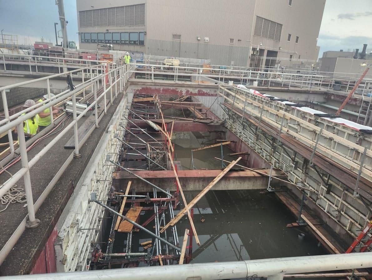
Deep excavation alongside existing process structures at a lakeside wastewater facility: URETEK installed a chemical grout curtain at the soil-structure interface to control groundwater during construction
A major wet-weather treatment expansion at a municipal wastewater facility on a Great Lakes shoreline required substantial below-grade excavation directly alongside existing concrete process structures. On a lakeshore site the water table is high, and groundwater entering the excavation would interfere with digging and with the construction that followed.
The harder constraint was what controlling that water could do to the neighbors. Broadly dewatering the site to hold groundwater back risks drawing down the surrounding soils, and that drawdown can settle or laterally move adjacent structures. The project team needed to manage flow into the excavation while limiting how far drawdown reached beyond it.
The work also had to proceed alongside an operating facility, on a construction schedule, with existing tanks and buried structures only feet away. Any groundwater-control method that meant heavy disturbance next to those structures was a problem in its own right. What the site called for was a way to seal water at the excavation itself, not across the whole site.
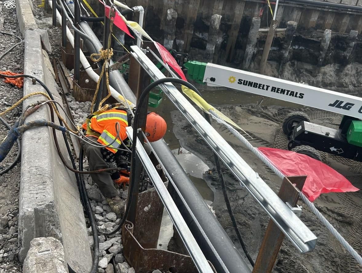
Injection lines staged along the excavation wall: the grout curtain was placed through the existing structure in a controlled, low-pressure sequence along an approximately 244-foot alignment
Broad dewatering, pumping the site down with well points or deep wells, is the common way to keep an excavation dry. Here it worked against the project: lowering the water table across the site is exactly what could settle the adjacent tanks. The need was to cut off flow into the excavation without drawing the whole area down.
Physical cutoff walls and heavy injection methods (for example, the jet grouting the project initially contemplated) are disruptive to install hard against live, existing concrete structures. And cement- or particle-based grouts are too viscous to enter the fine soil voids, fissures, and joints where water actually travels, so they cannot reliably seal those pathways.
What the site called for was a low-viscosity chemical grout that could permeate those fine pathways and form a lower-permeability zone right at the soil-structure interface, placed with enough control to leave the adjacent structures undisturbed. That is what a through-structure chemical grout curtain delivers.
Working with the general contractor and under the direction of a licensed professional engineer, URETEK designed and installed a chemical grout curtain at the soil-structure interface. The plan placed a continuous lower-permeability zone in the soils outside and beneath the existing structure along an approximately 244-foot alignment, concentrating treatment at the wall, floor, corner, and conduit interfaces where water pathways could reach the excavation.
Crews drilled a pattern of holes completely through the existing walls and floor and into the soil beyond, fitted each hole with a mechanically sealed packer, and injected a low-viscosity chemical grout. Holes were spaced roughly 18 to 24 inches apart horizontally and 12 inches vertically, staggered row to row for coverage, and carried at least two rows onto the floor to seal the wall-and-floor joint. Localized deeper injections reached about 10 feet where called for, and the pattern extended around a buried concrete conduit.
Placement was deliberately slow and low-pressure. Injection began at the lowest row and progressed upward one row at a time, so grout would permeate the available voids and travel along the structure rather than displace the surrounding soil. Pumping pressures were held as low as practical, and grout travel was monitored packer to packer, continuing until the design quantity was placed.
The curtain depended on a grout that could reach where water does. The material was a low-viscosity chemical grout, with a mixed viscosity on the order of 2 to 5 centipoise and an adjustable gel time. Low viscosity let it enter the fine soil voids and concrete fissures that thicker, particle-bearing grouts cannot, and the adjustable set time let crews tune the reaction to site temperature and conditions so the grout traveled into the pathways before it gelled.
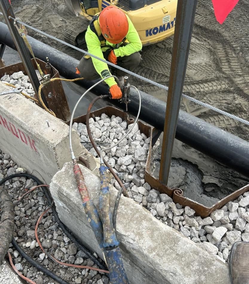
Controlled, low-pressure injection through a sealed packer: grout was placed slowly, bottom row first, so it permeated the voids along the structure rather than displacing the surrounding soil
The figures that defined this curtain came from the engineer’s design and the project’s acceptance procedure. Because a subsurface curtain cannot be seen once it is in place, those numbers, and the field test that checked them, are how its adequacy was judged.
The design placed treatment along an approximately 244-foot alignment (a submitted-plan quantity), on a staggered grid of holes roughly 18 to 24 inches apart horizontally and 12 inches on center vertically, carried at least two rows onto the floor and extended around a buried conduit, with localized injections reaching about 10 feet where required.
Placement was governed by control, not volume: pumping pressures held as low as practical (not exceeding roughly 300 psi), a placement rate on the order of 6 to 9 minutes per gallon, and typical coverage near 6 to 9 square feet of wall per gallon, with grout travel confirmed packer to packer along each row.
Acceptance was numerical. The specification required falling-head testing at a minimum of one location by an independent party: a 5-inch borehole drilled to the injection depth, saturated for at least 12 hours, then refilled and monitored for two hours. A water-level drop of one inch or less met the criterion; a greater drop triggered secondary grouting and re-testing.
The program delivered an engineered groundwater cutoff at the structure, verified against a defined standard, so construction could proceed.

Groundwater controlled at the structure. A lower-permeability grout curtain was installed at the soil-structure interface along the approximately 244-foot alignment, sealing the wall, floor, corner, and conduit pathways where water could reach the excavation.
Adjacent structures protected. Sealing flow at the interface with low-pressure permeation, rather than broadly dewatering the site, kept groundwater control focused at the excavation and away from the drawdown that can move nearby structures.
Verified against a defined criterion. Effectiveness was checked by independent falling-head testing to a numerical threshold, a one-inch maximum water-level drop over two hours, rather than by observation alone.
A built-in contingency. The acceptance procedure carried a clear trigger: if a location did not meet the threshold, secondary grouting followed and the zone was re-evaluated, so the curtain was confirmed, not assumed.
Minimal disturbance to an operating facility. Drilling small through-structure holes and injecting at low pressure let the work proceed hard against existing tanks and a live facility, without heavy excavation or cutoff-wall installation beside them.
Match the grout to the pathway. Water moves through fine voids, fissures, and joints. A low-viscosity chemical grout permeates those openings where cement- or particle-based grouts cannot, which is what makes a curtain at the interface effective.
Cut off flow without drawing down the neighbors. On sites where adjacent structures are settlement-sensitive, sealing groundwater at the excavation with a grout curtain avoids the broad dewatering that causes drawdown-induced movement.
Treat the interface, and the joints. Concentrating injection at the wall, floor, corner, and conduit interfaces, and carrying rows onto the floor to seal the wall-and-floor joint, closes the specific pathways water uses rather than treating a broad area.
Verify what you cannot see. A subsurface curtain’s continuity cannot be observed directly, so a numerical field test with a defined acceptance threshold and a secondary-grouting trigger is what turns it from assumed to confirmed.
If you are excavating near existing structures on a high-water-table site, where dewatering could settle what is next door, URETEK can help. We design and install chemical grout curtains that seal groundwater at the structure, with minimal disturbance to what is already there. We will assess your subsurface and structures, design a targeted injection program under professional engineering direction, and verify the result with defined field testing, so your team can excavate with groundwater under control.

 800-240-7868


